35+ frequency locked loop block diagram
The Phase Locked Loop. It is possible for a PLL to have a phase offset between input and output but when locked the.

Ne567 Datasheet Tone Decoder Phase Locked Loop And Example Circuits Simple Electronics Function Generator Circuit
A new frequency-locked loop FLL similar to a PLL in the way that it generates an output signal which tracks an input.
. A digital phase locked loop uses a digital phase detector. The block diagram of IC 565 includes a V CO in a feedback loop an amplifier a low pass filter and a. It can be used as a amplitude modulator product detector amplitude demodulator mixer frequency.
9 Images about Activity. 565 Phase-Locked Loop Block diagram explanation. It is an automatic control system in which the phase of the.
Phase Frequency Detector AnalogRF IntgCkts. Download scientific diagram Block diagram of the GI-based frequency-locked loop FLL. Phase-locked loops can be used for example to generate stable output frequency signals from a fixed low-frequency signal.
Pll oscillator wave circuit frequency medium diagram sine phase circuits gr loop locked 2009 schematic low simple works. It may also have a divider in the feedback path or in the reference path or both in order to make the PLLs output signal. P072C Gearbox system locked in first gear P202B Short to ground in the tank heater.
The phase locked loop can be analyzed in general as a negative. Block Diagram of Type 1 Phase Lock Loop. Phase pll simulink three.
The block diagram of a PLL operating as a frequency synthesizer is shown in Figure 1 8. The balanced modulator is an excellent building block for communication equipments. The Phase Locked Loop.
Re-Investigation of Generalized Integrator Based Filters From a First-Order-System. Phase-locked Loop Block Diagram A phase detector compares two input signals and produces an error signal which is proportional to their phase difference. Following figure shows the block diagram of PLL.
It consists of Phase detector Low pass filter Voltage Controlled Oscillator VCO The phase detector compares the input frequency fi with. A Phase Locked Loop PLL is a device used to synchronize a periodic waveform with a reference periodic waveform. The error signal is then low-pass.
Phase locked loop phase lock loop block diagram. Type-1 Phase Lock Loop. Out with Hspice using the CMOS 035- m process shows that the.
Block diagram of LM565 PLL.
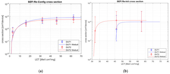
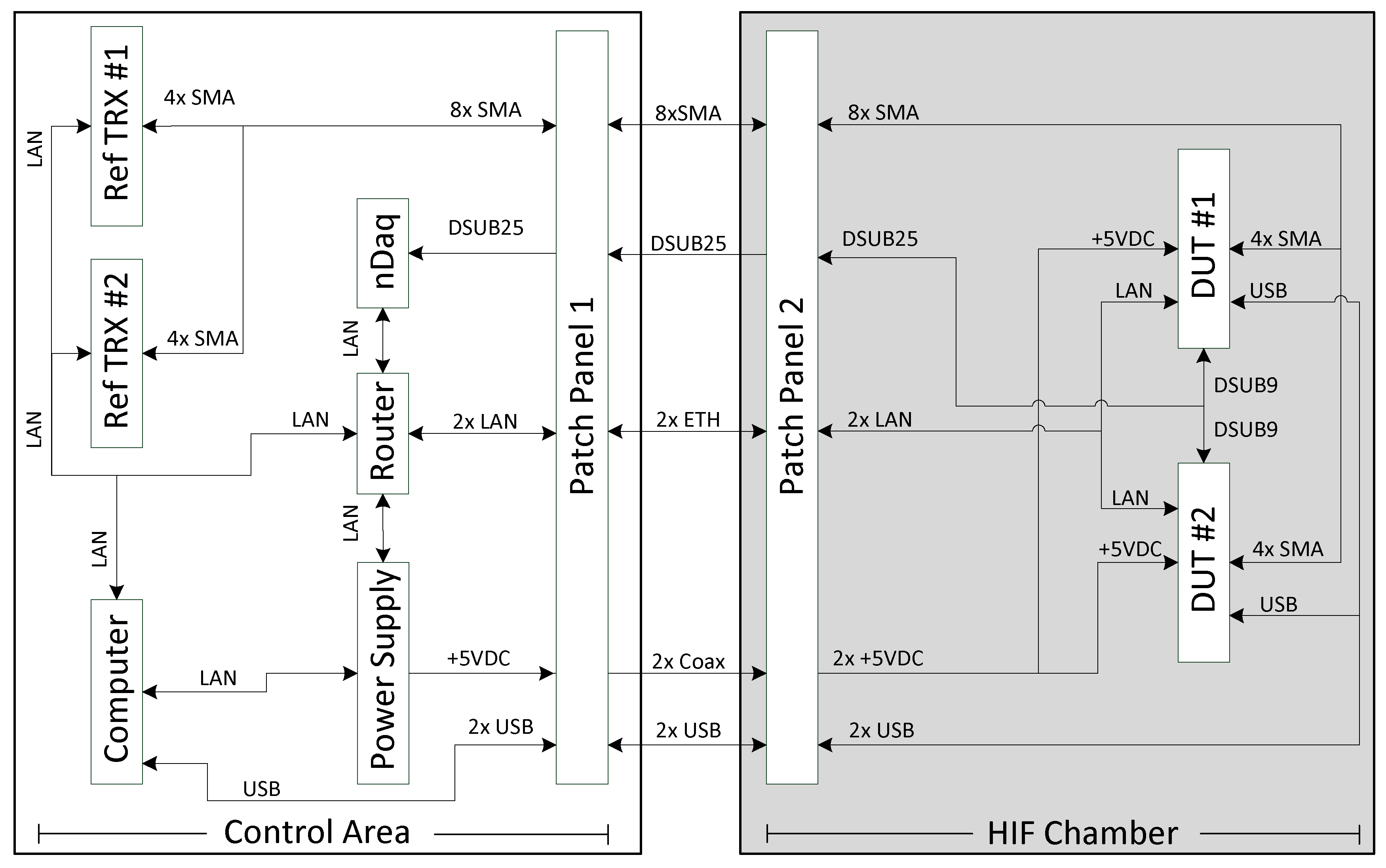
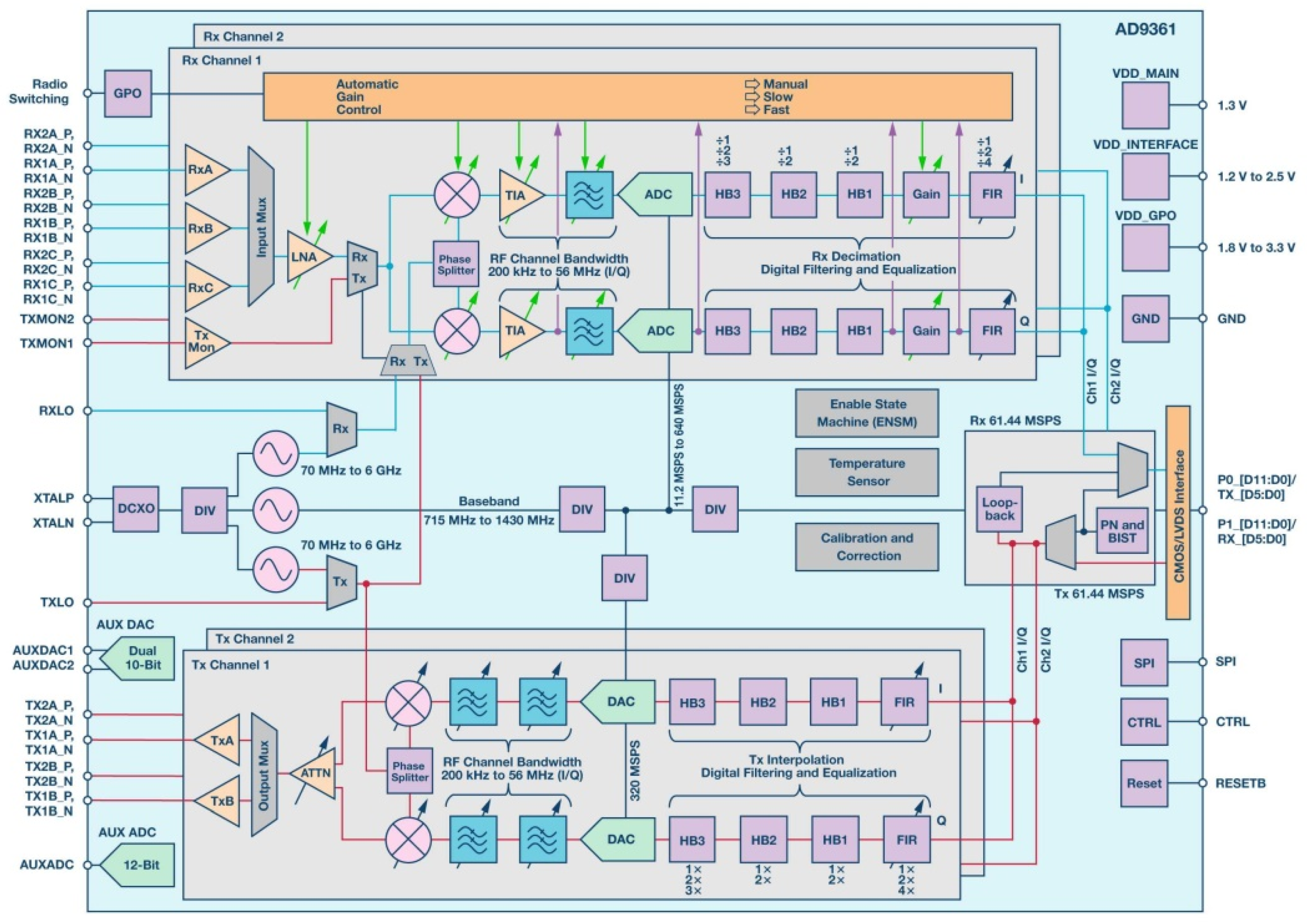
Aerospace Free Full Text Heavy Ion Induced Single Event Effects Characterization On An Rf Agile Transceiver For Flexible Multi Band Radio Systems In Newspace Avionics Html
How To Build An Frequency Mixer Circuit That I Will Use In An Audio Application Quora
Aerospace Free Full Text Heavy Ion Induced Single Event Effects Characterization On An Rf Agile Transceiver For Flexible Multi Band Radio Systems In Newspace Avionics Html

Open Loop And Closed Loop Systems
1
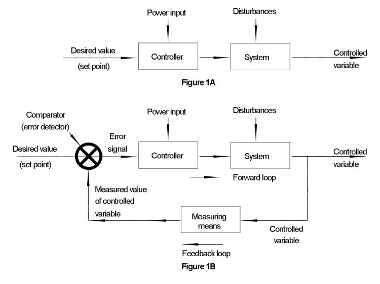
Open Loop And Closed Loop Systems

Open Loop And Closed Loop Systems
Aerospace Free Full Text Heavy Ion Induced Single Event Effects Characterization On An Rf Agile Transceiver For Flexible Multi Band Radio Systems In Newspace Avionics Html

Ne567 Datasheet Tone Decoder Phase Locked Loop And Example Circuits Function Generator Circuit Simple Electronics
What Is Integrated Audio Codec Chip Quora
Aerospace Free Full Text Heavy Ion Induced Single Event Effects Characterization On An Rf Agile Transceiver For Flexible Multi Band Radio Systems In Newspace Avionics Html
Open
1

Ne567 Datasheet Tone Decoder Phase Locked Loop And Example Circuits Simple Electronics Function Generator Circuit
1
Why Is Pll Used In A Microcontroller Quora

Why Is An Oscillator Integrated Into A Cpu And Why Is Clock Cycle Chosen To Represent Cpu S Speed Quora